Noted transportation reporter, Don Phillips, in the September 2015 issue of Trains magazine shared some thoughts about engineer Brandon Bostian. Basically, it is a mystery as to what happened to have provoked Bostian's acctions on May 12, 2015. Phillips writes that Mr. Bostian has the respect of the National Transportation Safety Board investigators. He is a "by-the-book railroader." He has cooperated fully.
The frustrating thing is that Mr. Bostian has had memory loos. He is unable to provide the whole picture.
The memory loss could have resulted from the trauma of the accident. There has been speculation by some that an undiagnosed medical condition might have been contributory. Petit mal seizure? A difficult to diagnose epileptic event? It is speculation.
The investigators, Phillips reports, have determined no problems with the track or roadbed. Bostian applied the brakes before the derailment.
Bostian's cell phone was not sending or receiving a signal at or near the time of the accident.
Phillips wrote that the hole in the windshield was determined by the FBI to not have been a result of bullet. The investigation continues as to the cause of the windshield hole. It did not exist when the train left 30th Street Station.
Further speculation has developed around the throttle in the locomotive operated by Bostian. His previous run during his workday was in a locomotive with the throttle that was a reverse configuration. Was there an impact to the windshield of sufficient impact to have startle and frightened Bostian to have moved the throttle the wrong direction causing him to accelerate. The capability of the locomotive's acceleration is remarkable. So, might it be determined that sequence of events was windshield damage, acceleration, temporary confusion of judgement, brake application, derailment ending with Bostian's reaction to use his cellphone to call for aid?
Wednesday, August 19, 2015
Friday, May 29, 2015
Frankford Junction History
The curve at Frankford Junction was designed and built for the Connecting Railroad in 1864 and opened for service in July of 1867. The Connecting Railroad was later absorbed into the Pennsylvania Railroad. It was aptly named as it connected PRR tracks with railroad company tracks crossing New Jersey to the Port of New York. Operations were possible over the slightly wider gauge of the new Jersey Railroads using cars with wide treads. The PRR was standard gauge of 4 feet 8 and a half inches. The New Jersey roads were 4 feet 10 inches.
The historical civil engineering represented by the curve is totally inadequate for today or the future.
(See Churella, The Pennsylvania Railroad Volume I at page 299.)
The historical civil engineering represented by the curve is totally inadequate for today or the future.
(See Churella, The Pennsylvania Railroad Volume I at page 299.)
Comments May 12 Amtrak Derailment Frankford Junction, Philadelphia
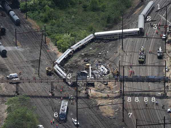
(Click on photo for full size of photo and data.) Here is a photo of the May 12, 2015, Amtrak derailment at the Frankford Junction curve in Philadelphia. Numbers 1, 2 and 3 identify parts of the fractured structural steel beam broken by the derailing train colliding with it as it passed. 4 (to the right of 5) identifies the crumpled remains of the first car behind the locomotive. 4 is in the center of the folded car with cranes to the left and right. 5 is the second car of the reaming six car string. The specially designed passenger car couplers did their job for the six cars as the cars did not separate. Had they had been connected with freight couplers the cars would have parted. Since about 1910 USA passenger cars have been designed for the frame to withstand 800,000 pounds of buff force. No other country has such a standard. 6 is the locomotive. Its right side headlight was damaged. 7 is the outside rail on the curve. It is higher than the inside rail opposite. That is referred to as the super elevated curve. Super elevation allows for faster speed through a curve like a race car track. The curve was rated at 50 miles per hour by the original owner and builder, the Pennsylvania Railroad. The current owner, Amtrak also has a 50 mile per hour speed restriction on the curve. The steel beam above and across the tracks at 8 suspends an electric wire above each track. A spring loaded device on the locomotive with a roller at the top contacts the wire and collects electric power to propel the electric motors driving the locomotive. The wires and steel beam supports are called catenary. I think that the locomotive grazed the catenary support enough for the first car to fully collide and fold. The locomotive separated and came to rest at 6. The firt car was pushed by the following cars to 4. As soon as the air brake line was severed from the locomotive the string of cars brakes activated explaining why the last two remained upright as the energy of the cars dissipated . Centrifugal force took the equipment to the right on a left curve.
Subscribe to:
Posts (Atom)

